Before installing the module
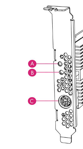
Back panel

| Label | Description |
|---|---|
A |
Status LED |
B |
Recovery mode button |
C |
A mini-DIN connector for connecting a smart card reader. |
Module pre-installation steps
Check the module to ensure that there is no sign of damage or tampering:
-
Check the epoxy resin security coating for obvious signs of damage.
-
If you intend to install the module with an external smart card reader, check the cable for signs of tampering. If evidence of tampering is present, do not use and request a new cable.
Fitting a module bracket
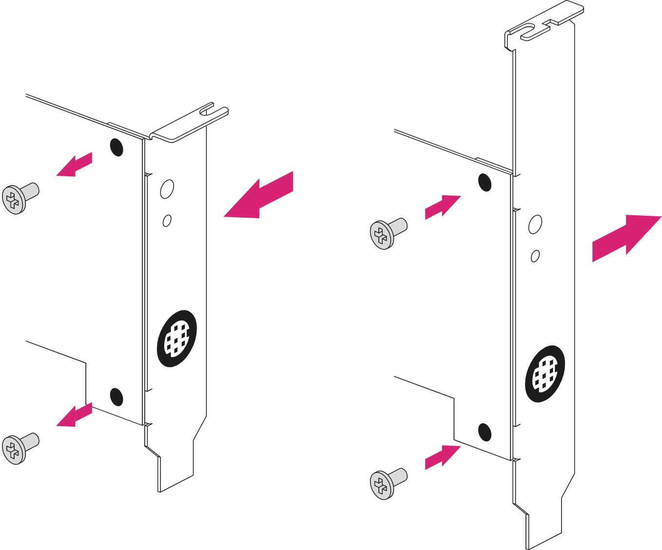
Before installing a module in a PCI Express card slot, you may have to replace the bracket if it is not the same height as the slot. Both full height and low profile brackets are supplied with the module.
Do not touch the connector pins, or the exposed area of the module without taking electrostatic discharge (ESD) precautions.

To fit the bracket to the module:
-
Remove the two screws from the solder side of the module.
-
Remove the incorrect bracket.
-
Fit the correct bracket to the component side of the module.
-
Insert the two screws into the solder side of the module to secure the bracket. Do not over tighten the screws.
User Replaceable items
If the module has been removed so that a part can be replaced, follow these procedures before installing the module. If no parts need replacing, proceed to Installing the module.
Replace the battery
| Please follow battery disposal guidelines in the installation manual. |
Required tools
-
Small non-conductive tweezers
Required part
-
Orderable part number: SOLOXC-REP-BATT (Replacement battery)
To remove and replace the battery:
-
Power off the system and while taking ESD precautions, remove the module.
-
Place the module on a flat surface.
-
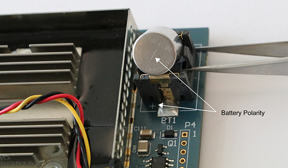
Using the tweezers, gently remove the battery from the BT1 connector.

-
Observing the polarity, install the replacement battery in the BT1 connector.
-
Re-install the module into the PCIe slot.