Installing an nShield Connect in a rack, cabinet, or shelf
This chapter describes how to install the nShield Connect in a rack, cabinet, or shelf. For more information about connecting the nShield Connect to the network, and configuring it for connection to one or more clients on the network, see the nShield Connect User Guide.
| Always handle modules correctly. For more information, see Handling an nShield Connect. |
Take due account of the weight and dimensions of the nShield Connect when selecting a location for storage or installation (see Handling an nShield Connect).
| You cannot install or configure the nShield Connect remotely. |
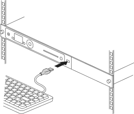
To install the nShield Connect in a 19” rack, follow the instructions supplied with your rack mounting kit.
To install the nShield Connect in a cabinet or a shelf, fit the four self-adhesive rubber feet (supplied with the HSM) to the bottom of the HSM.
An X is scored into the chassis at each of the four corners on the bottom of the HSM as a guide to placing the feet.
Connecting Ethernet, console and power cables
The nShield Connect is an Ethernet network device capable of supporting up to 100m of Ethernet cable. You must use a CAT5e UTP cable or better when connecting the HSM to a 100Mbit or 1Gbit Ethernet device. You must use a CAT3 cable or better for 10Mbit connections.
The connectors for Ethernet cables and mains power cables are at the rear of the nShield Connect.
Ensure that:
-
All power cables are routed to avoid sharp bends, hot surfaces, pinches, and abrasion.
-
You connect mains power cables to both the PSUs.
-
The rocker switch for each PSU is in the on position.
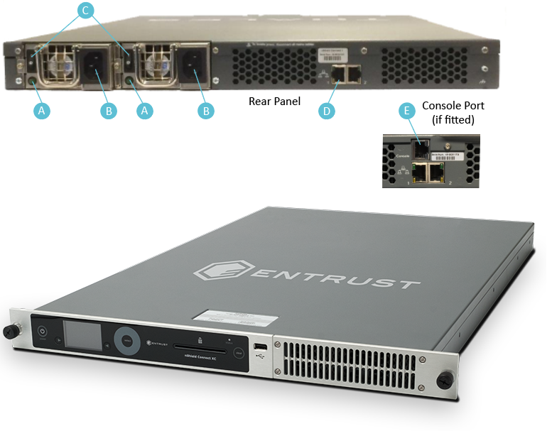
The following image shows the Ethernet, console and mains power connections:
| Key | Description |
|---|---|
A |
Green LED if on, confirms power is on and unit is not in Standby mode |
B |
Mains power connection |
C |
Rocker switch to turn PSU on and off |
D |
Ethernet port. Two Ethernet ports are available. Port 1 is the left-hand connector when the nShield Connect is viewed from the back |
E |
RJ45 port for a serial console cable |
| If you connect only one Ethernet cable to the nShield Connect, Entrust recommends that you connect it to Ethernet port 1. This is the left-hand Ethernet connector on the rear of the nShield Connect (shaded in the image). |
If the green LED is on, the PSU is operational and receiving power, and is not in Standby mode. If a power cable is not fitted correctly, or a rocker switch is not turned on, an audible warning is given and the orange warning LED on the front panel is turned on.
For more information:
-
Audible warnings, see Audible warning.
-
The orange warning LED, see Orange warning LED.
-
Identifying and replacing a faulty PSU, see the nShield Connect Power Supply Unit Installation Sheet.
Connecting the Serial Console
On supported nShield Connect hardware variants (see Model numbers) there is a serial console port that provides access to a serial console command line interface that enables remote configuration of the nShield Connect (See the nShield Connect User Guide).
The RJ45 connector for the serial cable is at the rear of the nShield Connect and is labelled Console (Connecting Ethernet, console and power cables. The connector can be directly connected to your client machine or connected to a serial port aggregator for remote access. For a specification of the serial cable required, see Serial Console cable pinout information. The serial port will operate at 9600 baud, 8 data bits, no parity, and 1 stop bit (9600/8-N-1).
| It is recommended to use a shielded cable for the serial connection as the EMI noise from other devices in vicinity may affect the communication over the serial connection. |
Serial Console cable pinout information
The pinout information for the RJ-45 to DB-9 cable to be used to access the nShield Connect Serial Console is provided in the table below:
| Signal | Console Port (DTE) RJ-45 Pin | Adapter DB-9 Pin | Signal |
|---|---|---|---|
CTS |
1 |
7 |
RTS |
DTR |
2 |
4 |
DSR |
TxD |
3 |
3 |
RxD |
GND |
4 |
5 |
GND |
GND |
5 |
5 |
GND |
RxD |
6 |
2 |
TxD |
DSR |
7 |
6 |
DTR |
RTS |
8 |
8 |
CTS |
Connecting the optional USB keyboard
Instead of using the controls on the front panel to configure the nShield Connect, you can use a US or UK keyboard. You might find a keyboard easier for entering dates and IP addresses. You connect the keyboard to the USB connector on the front of the nShield Connect.
Configuring an nShield Connect for your keyboard type
To configure an nShield Connect for your keyboard type, select System > System configuration > Keyboard layout and then choose the keyboard type you require.
When you have connected a keyboard and configured the nShield Connect for its use, you can enter numbers and characters directly into the display. See the User Guide for more about using a keyboard and keystroke shortcuts.