Client Software and module configuration
This chapter describes how to configure the internal security module of the Connect and the client to communicate with each other, after you have installed the HSM and the Security World Software.
For more information about installing the HSM, see the Installation Guide. If you are configuring an HSM and client for the first time, or you want to complete a basic installation quickly, see the Installation Guide.
| The Connect provides significant performance improvements, and can be deployed successfully with existing nShield products. Customers wishing to take advantage of these performance improvements must update their client machines with the latest Security World Software. |
About user privileges
Cryptographic security does not depend on controlling user privileges or access but maintaining the integrity of your system from both deliberate or accidental acts can be enhanced by appropriate use of (OS) user privileges.
There are three levels of user:
-
Superuser
-
nfast group user
-
normal
Typically, normal users can carry out operations involving Security Worlds, cardsets and keys, but not create Security Worlds, keys and cardsets.
nfast group users have enhanced access, enabling them to create Security Worlds, cardsets and keys.
For example, encrypted copies of keys are held in kmdata (/opt/nfast/kmdata). Normal users only have read access to the files, whereas nfast group users have read and write access, enabling them to create and use keys.
nfast group users can also change the mode of an HSM remotely.
Superuser access (e.g., root) is required for such tasks as software installation, starting and stopping the hardserver and SNMP
About client configuration
| You can add more HSMs to a client and more clients to an HSM at any time. |
The HSM and a client communicate by means of the hardserver, which handles secure transactions between the HSM and applications that run on the client. You must configure:
-
Each client hardserver to communicate with the HSM that the client needs to use
-
The HSM to communicate with clients that are allowed to use the HSM.
Information about the current configuration of the HSM or a client is stored in configuration files that are stored in specified file systems on the clients and on the HSM. For more information about the contents of configuration files, see nShield Connect and client configuration files.
For information about configuring the HSM by importing an edited configuration file, see About user privileges.
Remote file system (RFS)
Each HSM must have a remote file system (RFS) configured. The RFS contains master copies of all the files that the HSM needs:
-
The HSM configuration file
-
Feature-enabling certificates
-
The encrypted Security World and key data for Security Worlds created on the HSM.
The RFS normally resides on a client computer, but it can be located on any computer that is accessible on the network.
For more information about setting up the remote file system, see Configuring the Remote File System (RFS).
HSM configuration
The data that defines the configuration of the HSM hardserver is stored in a file on the HSM. This file is automatically:
-
Updated when the HSM is configured from the front panel
-
Exported to the remote file system (RFS) directory.
Each HSM has separate configuration files on the RFS, stored in the directories with names of the form
/opt/nfast/kmdata/hsm-ESN/config
where ESN represents the electronic serial number of the HSM from which the files were exported.
These directories can contain the following files:
| Option | Description |
|---|---|
|
The master configuration file. This contains the current configuration for the HSM. It is always present in the directory. |
|
An alternative configuration file saved by the system. |
|
A hand-edited configuration file that can be read by the HSM. |
You normally configure the HSM using the front panel controls. However, in some cases (for example, if you need to configure an HSM remotely, or if you are importing a number of clients), you may prefer to edit the exported configuration file and then re-import the file into the HSM. For more information, see:
Client configuration
The data that defines the configuration of the client hardserver is stored in a file on the client’s file system.
You must load the configuration file for the configuration to take effect. For information about loading a client configuration remotely, see Remote configuration of additional clients.
You can configure a client to use multiple HSMs. All the HSMs configured for use by a client can fail over if the application that uses them is set up appropriately.
For more information about the contents of the client configuration file, see nShield Connect and client configuration files.
| You can also configure the client’s hardserver by setting environment variables, as described in Setting environmental variables. Environment variable settings override settings in the client configuration files. |
Basic HSM and remote file system (RFS) configuration
After installing the HSM hardware and software, there are several HSM and RFS configuration tasks you must perform. You perform these RFS tasks before:
-
Creating the Security World and an Operator Card Set (OCS)
-
Completing the process of configuring the HSM and client to work together.
Configuring the Ethernet interfaces
The HSM communicates with one or more clients. Each client is an Ethernet connected computer that has the Security World Software installed and configured. You must supply Internet Protocol (IP) addresses for the HSM and the client. Contact your system administrator for this information if necessary.
To configure the Ethernet interfaces (IPv4 and IPv6), see the Connect Installation Guide.
Optionally configure hardserver interfaces
By default, the hardserver listens on all interfaces. However, you can alter the hardserver settings. Altering the hardserver settings would prove necessary, for example, if you wanted to connect one of the Ethernet interfaces to external hosts.
Ensure that you have configured the Ethernet interfaces on the HSM before attempting to configure the hardserver. See the Installation Guide for more information about configuring the Ethernet interfaces.
You can configure the following options to specify network interfaces on which the hardserver listens:
| Option | Description |
|---|---|
All interfaces |
This option (which is the default) specifies that the hardserver listens on all interfaces. |
IP address of interface #1 |
This option specifies that the hardserver listens only on interface 1. This option only appears if interface 1 has been configured. |
IP address of interface #2 |
This option specifies that the hardserver listens only on interface 2. This option only appears if interface 2 has been configured. |
Will not listen |
This option specifies that the hardserver does not listen on any interfaces. |
To define the interface and port on which the hardserver listens:
-
From the main menu, select System > System configuration > Hardserver config. The following screen appears:
Hardserver config Select network I/F hardserver listens on: All interfaces Select TCP port: 9004 CANCEL FINISH -
Select the network interfaces on which the hardserver is to listen.
For security reasons, do not allow the hardserver to listen on any interface that is to connect to the public Internet. -
Press the Select button to move to the TCP port field, and set the port on which the hardserver is to listen. The default is 9004.
Make sure that your firewall settings are consistent with your port settings. See the Installation Guide for more about firewall settings. -
When the network interface and port are correct, press the right-hand navigation button.
-
Press the right-hand navigation button again to continue.
-
You are asked if you wish to reboot the system now or later. Press the right-hand navigation button to reboot now.
Configuring the Remote File System (RFS)
The RFS contains the master copy of the HSM Security World data for backup purposes. The RFS can be located on either a client or another network-accessible computer where the Security World Software is installed. If the RFS is on a client, the same file structure also contains the configuration files for that client.
We recommend that you regularly back up the entire contents of the RFS. The
kmdata
directory is required to restore the HSM, or a replacement, to its current state, in case of failure.
|
You can specify a new remote file system, and modify or delete an existing remote file system configuration. To create or modify a remote file system configuration, specify the IP address of the computer on which the file system resides.
| You must have created an RFS on the client computer before you specify the IP address of the client. |
For more information about the RFS and its contents, see:
The HSM must be able to connect to TCP port 9004 of the RFS. If necessary, modify the firewall configuration to allow this connection on either the RFS itself or on a router between the RFS and the HSM.
Obtain the following information about the HSM before you set up an RFS for the first time:
-
The IP address
-
The electronic serial number (ESN)
-
The hash of the
KNETI key (HKNETI). TheKNETI key authenticates the HSM to clients. It is generated when the HSM is first initialized from factory state.
If your network is secure and you know the IP address of the HSM, you can use the anonkneti utility to obtain the ESN and hash of the KNETI key by giving the following command on the client computer.
For guidance on network security, see the nShield Security Manual.
anonkneti <Unit IP>In this command, <Unit IP> is the IP address of the HSM, which could be one of the following:
-
An IPv4 address, for example
123.456.789.123. -
An IPv6 address, for example
fc00::1. -
A link-local IPv6 address, for example
fe80::1%eth0. -
A hostname.
The command returns output in the following form:
A285-4F5A-7500 2418ec85c86027eb2d5959fef35edc5e1b3b698fIn this example output, A285-4F5A-7500 is the ESN and 2418ec85c86027eb2d5959fef35edc5e1b3b698f is the hash of the KNETI key.
Alternatively, you can find this information on the HSM startup screen. Use the touch wheel to scroll to the appropriate information.
When you have the necessary information, set up an RFS as follows:
-
Prepare the RFS on the client computer (or another appropriate computer) by running the following command on that computer:
rfs-setup --force <Unit IP> <EEEE-SSSS-NNNN> <keyhash>
In this command:
-
<Unit IP> is the IP address of the HSM.a
-
<EEEE-SSSS-NNNN> is the ESN of the HSM.
-
<keyhash> is the hash of the
KNETI key.
-
-
On the HSM display screen, use the right-hand navigation button to select System > System configuration > Remote file system, and enter the IP address of the client computer on which you set up the RFS.
Leave the port number at the default setting of 9004.
To modify or delete an RFS at a later date, select System > System configuration > Remote file system, and then select the required action.
You can allow non-HSM hardware security modules to access the remote file system and share Security World and key data that is stored in the
kmdata
directory in the same way as the HSM.
Clients that access data in this way are described as cooperating clients.
To configure client cooperation, you need to know the details of each client including IP address and ESN.
|
After you have defined the remote file system, the HSM configuration files are exported automatically to the remote file system. For more information about configuration files, see nShield Connect and client configuration files.
Configuring log file storage
You can choose to store log files on both the HSM and RFS or on the HSM only.
To configure log file storage, use the right-hand navigation button to select System > System configuration > Log config. Then select one of:
-
Log to store log files on the HSM only.
-
Append to store log files on both the HSM and remote file system.
We recommend selecting Append because if you select Log you can only view the log file from the Connect front panel. Moreover, the log file stored on the HSM is cleared every time it is powered down.
You may also additionally configure the logs to be sent to a remote syslog server, see Configuring Remote Syslog.
Setting the time and date
If you do not intend to use NTP time synchronization, set the time and date as described in this section. If you configure the Connect to use NTP time synchronization, then the time and date will be maintained by NTP.
To set the time and date on the HSM as UTC:
-
Use the right-hand navigation button to select and display the System menu:
1-1 System configuration System information Login settings Upgrade system Factory state Shutdown/Reboot BACK SELECT -
Select System configuration to display the System configuration menu:
1-1-1 Network config Hardserver config Remote file system Client config Resilience config Config file options BACK SELECT -
Use the touch wheel to move the arrow to Date/time setting, and press the right-hand navigation button to select it. The Set system date screen is displayed:
Set system date Please enter the current UTC date as DD/MM/YYYY: 27/ 5/2013 CANCEL NEXT -
For each date field, use the touch wheel to set the value and move the cursor to the next field.
When you have completed all the fields, press the right-hand navigation button to confirm the date. The Set system time screen is displayed:
Set system time
Please enter the
current UTC time as
hour/mins/seconds:
 18:08:19
CANCEL              FINISH
Setting the time and date of the HSM as UTC does not reset the value of the Real Time Clock (RTC) on the HSM. The UTC date and time settings are used only in log messages.
Keyboard layout
You can connect a keyboard to the USB connector on the Connect front panel. This enables you to control the Connect using a special set of keystrokes instead of the standard front panel controls.
You can connect either a US or a UK keyboard. To configure the Connect for your keyboard type, select System > System configuration > Keyboard layout and then choose the keyboard type you require.
Configuring the Connect to use the client
You must inform the HSM hardserver of the location of the client computer.
You can configure the connection to use secure client authentication, either with an nToken installed in the client or with software-based authentication. If a client attempts to connect to the Connect when secure client authentication is in use, the HSM not only examines the client’s IP address, but also requires the client to identify itself using a signing key.
| If an nToken is installed in a client, it can be used to both generate and protect a key that is used for the impath communication between the Connect and the client. Thus a strongly protected key is used at both ends of the impath. |
| Software-based authentication is only supported from version 12.60. Previously enrolled clients using software-based authentication will need to be re-enrolled if an earlier version of Security World software is installed. |
The client configuration process varies slightly depending on whether you are enrolling the client with or without secure client authentication:
-
On the Connect front panel, use the right-hand navigation button to select System > System configuration > Client config > New client.
The following screen is displayed:
Client configuration Please enter your client IP address: CANCEL NEXT -
Enter the IP address of the first client, and press the right-hand navigation button.
-
Use the touch wheel to confirm whether you want to save the IP or not, and press the right-hand navigation button.
Client configuration Do you want to save the IP in the config? (No for dynamic client IPs) No Back Next -
Use the touch wheel to display the type of connection between the internal security module of the Connect and the client.
Client configuration

Please choose the
client permissions

    Unprivileged

BACK                NEXT
The following options are available:
Option Description Unprivileged
Privileged connections are never allowed.
Priv. on low ports
Privileged connections are allowed only from ports numbered less than 1024. These ports are reserved for use by root Linux.
Priv. on any ports
Privileged connections are allowed on all ports.
A privileged connection is required to administer the Connect. If privileged connections are allowed, the client can issue commands (such as clearing the HSM) which interfere with its normal operation. We recommend that you allow only unprivileged connections unless you are performing administrative tasks. -
When you have selected a connection option, press the right-hand navigation button.
The following screen is displayed:
Client configuration

Do you want secure
authentication enabled
on this client?

          Yes
 BACK             NEXT
You must choose whether to disable or enable secure authentication when enrolling the client.
To enroll the client without secure authentication, select No and press the right-hand navigation button.
By selecting No, authentication of the client will be based on the IP address only.
If you enable secure authentication, you must choose whether to use nToken or software-based authentication.
| nToken authentication is recommended, if available. See also Configuring the Connect to use the client. |
nToken authentication
To enroll the client with nToken authentication, you must first confirm the nToken authentication key:
-
On the client, open a command line window, and run the command:
ntokenenroll -HThis command produces output of the form:
nToken module #1
nToken ESN:       3138-147F-2D64
nToken key hash: 691be427bb125f38768638a18bfd2eab75623320
You will need to compare the returned key hash with a value reported on the Connect display in a subsequent step. Write the hash down, or ensure that you can see the key hash displayed on the Connect as you work on the client. -
On the Connect, enter the number of the port on which the client is listening and press the right-hand navigation button. (The default is 9004.)
You will now be presented with a list of ESN options. Select the ESN that matches the output from
ntokenenrollcommand, produced above.After selecting an ESN, the Connect display will show information of the following form, identifying the selected nToken by its ESN and displaying a key hash:
Client reported the software key hash: 691be427bb125f387686 38a18bfd2eab75623320 Is this EXACTLY right? CANCEL CONFIRM -
Compare the hash displayed by the Connect with the hash that was previously reported by
ntokenenrollon the client. If there is an exact match, press the right-hand navigation button to configure the client. -
The Connect displays a message reporting that the client has been configured. Press the right-hand navigation button again.
Software-based authentication
To enroll the client with software-based authentication, you must first confirm the software authentication key:
-
On the client, open a command line window, and run the command:
anonkneti -m0 127.0.0.1This command returns the software key hash:
d4c3d757a67416cb9ba31f33febd6ead688629e5You will need to compare the returned key hash with a value reported on the Connect display in a subsequent step. Write the hash down, or ensure that you can see the key hash displayed on the Connect as you work on the client. -
On the Connect, enter the number of the port on which the client is listening and press the right-hand navigation button. (The default is 9004.)
You will now be presented with a list of ESN options, including a
Software keyoption if software-based authentication is provided by the client’s hardserver. -
Select the
Software keyoption.After selecting the
Software keyoption, the Connect display will show information of the following form, displaying the software key hash:Client reported the software key hash: 691be427bb125f387686 38a18bfd2eab75623320 Is this EXACTLY right? CANCEL CONFIRM -
Compare the hash displayed by the Connect with the hash that was previously reported by
anonknetion the client. If there is an exact match, press the right-hand navigation button to configure the client. -
The Connect displays a message reporting that the client has been configured. Press the right-hand navigation button again.
To modify or delete an existing client, select System > System configuration > Client config and perform the appropriate procedure.
If you want to use multiple clients with the Connect, you must enable additional client licenses (see Enabling optional features). When you have additional client licenses enabled, to configure more clients, repeat the appropriate steps of the procedure described in this section for each client.
Remote configuration of additional clients
After you have configured the first client for your Connect and provided you have enabled auto push, you can add additional clients remotely.
| Before you can use multiple clients with the Connect, you must enable the additional clients as described in Enabling optional features. |
To add clients remotely:
-
Save the configuration file of the Connect
/opt/nfast/kmdata/hsm-ESN/configasconfig.newin the same directory. -
Edit the configuration file
config.newand add a new entry to thehs_clientssection to contain the details of the client to be added.The following two entries must exist in the configuration file:
addr=<client_IP>
clientperm=permission_type
Where:
<client_IP>can be either the IP address of the client or0.0.0.0,::, or blank if the HSM is to accept clients identified by their key hash instead of their IP address.0.0.0.0or::, and blank result in the same behavior. You can only use them in the configuration file, you cannot enter these values in the front-panel user interface.The default is blank.
If you set both the
<client_IP>field (the client’s IP address) and the key hash, the HSM must identify clients from both of these fields.permission_typedefines the type of commands the client can issue (unpriv,privorpriv_lowport).-
If the client is using an nToken, two additional entries will need to be added to the configuration file:
esn=nToken_ESN
keyhash=nToken_keyhash
Where
nToken_ESNis the ESN of the client’s nToken andnToken_keyhashis the hash of the key that the client’s nToken should authenticate itself with. -
If the client is using software-based authentication, one additional entry will need to be added to the configuration file:
keyhash=software_keyhashWhere
software_keyhashis the hash of the software generated key that the client should authenticate itself with. TheESNentry must be blank or omitted for software-based authentication.Each client entry after the first must be introduced by a line consisting of one or more hyphens.
-
-
Load the updated configuration file on to the Connect. To do this, run the following command:
cfg-pushnethsm --address=<module_IP_address> <new_config_file>In this command,
<module_IP_address>is the IP address of the Connect and<new_config_file>is the location of the updated configuration file (config.new). Ifmodule_IP_addressis an IPv6 address, then enclose it within square brackets, for example[fc00::1].With auto push enabled, you can load the configuration file using the Connect front panel. The configuration file (
config.new) must be in the directory/opt/nfast/kmdata/hsm-ESN/configon the remote file system. To do this, select System > System configuration > Config file options > Fetch configuration.An SEE machine cannot be installed or configured using the fetch configuration option from the front panel. The auto push feature must be used for this. See Remotely loading and updating SEE machines for more information.
Configuring client computers to use the Connect
Each client computer must be configured to use the internal security module of your Connect. There are two methods for achieving this:
-
Enrolling the client with the configuration file.
-
Enrolling the client with command-line utilities.
Enrolling the client with the client configuration file
The client configuration files are in the directory
/opt/nfast/kmdata/config
on the client computer’s file system.
For this release, you must generate a new client configuration file to take advantage of the new functionality.
To generate a new client configuration file, back up your existing configuration file and run the command cfg-mkdefault. This generates a template for the configuration file into which you can copy the settings from your old configuration file.
|
The nethsm_imports section defines the network HSMs that the client imports (See nethsm_imports). It can also be set up by the nethsmenroll utility.
-
Edit the following mandatory fields:
local_module,remote_ip,remote_esn,remote_keyhashandprivileged. The default value forremote_keyhash(40 zeros) specifies that no authentication should occur. -
The
ESNandhashof the HSM to import can be retrieved by running the commandanonkneti remote_ip -
If the client is to be enrolled with an nToken, open a command line window, and run the command:
ntokenenroll --H. This command produces output of the form:nToken module #1 nToken ESN: 3138-147F-2D64 nToken key hash: 691be427bb125f3876838a18bfd2eab75623320 -
Enter the nToken’s
ESNin the fieldntoken_esnin the config file. -
Each HSM entry after the first must be introduced by a line consisting of one or more hyphens, i.e.
---. -
At the command line run the command
cfg-reread, to reload the hardserver’s configuration. -
Verify that the client can use the Connect by running
enquiry, which reports the HSM’s status.
If the client is to be enrolled with either software-based authentication or no authentication, the ntoken_esn field must be left empty.
|
For information about configuration file contents, see nShield Connect and client configuration files.
Enrolling the client from the command line
The nethsmenroll command-line utility edits the client hardserver’s configuration file to add the specified Connect.
For more information about the options available to use with nethsmenroll, read the following section Client configuration utilities, or run the command:
nethsmenroll --helpTo retrieve the Connect’s ESN and HKNETI, run the command
anonkneti <Unit IP>This command produces output of the form:
3138-147F-2D64 691be427bb125f38768638a18bfd2eab75623320If the Connect’s ESN and HKNETI are not specified, nethsmenroll attempts to contact the HSM to determine what they are, and requests confirmation.
-
If you are enrolling the client with an nToken, run the command:
nethsmenroll --ntoken-esn <nToken ESN> [Options] --privileged <Unit IP> <Unit ESN> <Unit KNETI HASH> -
If you are enrolling the client without an nToken, i.e. software-based authentication or no authentication, run the command:
nethsmenroll [Options] --privileged <Unit IP> <Unit ESN> <Unit KNETI HASH>
These commands produce output of the form:
OK configuring hardserver's nethsm imports.Client configuration utilities
We provide the following utilities for client configuration:
| Utility | Description |
|---|---|
|
This utility is used to configure the client to communicate with the Connect. |
|
This utility is used to configure the client’s hardserver to enable TCP sockets. |
nethsmenroll
The nethsmenroll command-line utility edits the client hardserver’s configuration file to add the specified Connect.
If the Connect’s ESN and HKNETI are not specified, nethsmenroll attempts to contact the Connect to determine what they are, and requests confirmation.
Usage:
nethsmenroll [Options] --privileged <nShield Connect IP> <nShield Connect ESN> <nShield Connect KNETI HASH>| Options | Description | ||
|---|---|---|---|
|
Specifies the local HSM number to use (default is |
||
|
Causes the hardserver to request a privileged connection to the Connect (default |
||
|
The IP address of the nShield Connect, which could be one of the following:
|
||
|
Deconfigures the specified Connect. |
||
|
Forces reconfiguration of an Connect already known. |
||
|
Does not request confirmation when automatically determining the Connect’s
|
||
|
When the |
||
|
Specifies the port to use when connecting to the given Connect (default |
||
|
Specifies the |
config-serverstartup
The config-serverstartup command-line utility automatically edits the [server_startup] section in the local hardserver configuration file in order to enable TCP ports for Java and KeySafe.
Any fields for which values are not specified remain unchanged.
After making any changes you are prompted to restart the hardserver.
Run config-serverstartup using commands of the form:
config-serverstartup [OPTIONS]For more information about the options available to use with config-serverstartup, run the command:
config-serverstartup --helpConfiguring NTP in the Connect
The Connect has a standard NTP client that can be configured to support synchronization of system time on the Connect with one or more NTP servers. Network Time Protocol (NTP) is intended to synchronize all participating computers to within a few milliseconds of Coordinated Universal Time (UTC). System time on the Connect is independent of the Real Time Clock (RTC) in the HSM and is used for log messages and front panel display.
| Entrust recommends that the NTP Server(s) are trusted servers within your local network, not internet time servers. |
After configuring NTP the Connect has to be re-started for the configuration to take effect. When starting up after being configured, the NTP client can make a step change to the system time to bring it into line with that of the NTP server(s). At all other times, the NTP client will only slew (gradually change) the system time. When using NTP there should be no need to set the system time by setting time and date from the front panel of the Connect.
Before configuring NTP you must ensure the following:
-
auto push is enabled for the client computer you wish to use for configuring NTP, see Configuring auto push.
-
The client computer enabled for auto push is configured for Privileged connections, see Configuring the Connect to use the client, so that the Connect can be rebooted from the client computer.
Using the NTP configuration tool
NTP is configured using the cfg-pushntp utility on a client computer.
| Utility | Description | ||
|---|---|---|---|
|
This tool enables or disables NTP time synchronization on the specified Connect. When enabling NTP synchronization, the IP addresses of up to 3 NTP servers may be specified.
|
Usage:
cfg-pushntp -a ADDR [-p PORT -k -m MODULE] -1 ADDR [-2 ADDR -3 ADDR] enablecfg-pushntp -a ADDR [-p PORT -k -m MODULE] disableOptions:
| Field | Description |
|---|---|
|
Enable or disable NTP service on the Connect. |
|
IP address of Connect to configure NTP on. |
|
Set port to use to connect to the Connect (default=9004). |
|
Use KNETI to authenticate ourselves. |
|
Set the HSM to use for KNETI authentication.
The default is HSM 1. This option can only be used with the - |
|
IP address of NTP server. |
|
IP address of NTP server. |
|
IP address of NTP server. |
For example, running the command:
cfg-pushntp --address=192.30.100.150 --ntp1=192.23.24.256 enableReturns:
The requested NTP configuration changes have been uploaded and will take effect when the target Connect is restarted.Restarting the Connect
After configuring NTP, restart the Connect, for example see Using nethsmadmin to reboot an Connect. Once the Connect has rebooted and the syslog output is available, check that there are no NTP failures reported in the syslog output.
Configuring Remote Syslog
The Connect can be configured to send logs directly to a remote syslog server, listening on a User Datagram Protocol (UDP) port, by editing the remote_sys_log section of the config file.
This behavior can be configured in addition to storing the log files on the RFS (i.e. you can configure the logs to be sent to a remote syslog server regardless of whether the Connect logs are configured to be stored on the HSM or the RFS). For further information see Configuring log file storage.
There is no additional formatting of log messages (the logs sent are the same log messages that will appear on the unit or the RFS). It is the responsibility of the remote syslog server / SIEM application to format, sort and aggregate the incoming log messages.
To configure an nShield Connect to send logs to a remote syslog server:
-
In the
remote_sys_logsection of the config file for the remote module, add the following settings:If your configuration file predates the functionality to send logs to a remote syslog server, you will need to manually create a new config file section called remote_sys_log.remote_sys_log_ip=REMOTE_SYSLOG_SERVER_IP remote_sys_log_port=REMOTE_SYSLOG_SERVER_PORT -
Run the following command to push the new config file to the module:
cfg-pushnethsmIf you are using an older version of the Security World software with an Connect image that supports remote syslog, you will see this error message: unrecognized section name: 'remote_sys_log'. Use the following command to push the updated configuration file: cfgpushnethsh --forceIf you are using a version of the Security World software that supports remote syslog with an Connect image that does not support remote syslog, the configuration file will be pushed to the Connect but will be rejected by the Connect. You will see that the upgraded configuration file on the RFS is unchanged.
To turn off sending logs to a remote syslog server, remove the entries from the remote_sys_log section of the configuration file and push the updated configuration file.
Setting up client cooperation
If you do not need to allow multiple clients access to your remote file system (RFS), you only need to follow the instructions provided in Configuring the Remote File System (RFS) to initialize your RFS. If you need to allow other clients to access your RFS (that is, able to access the RFS to share key data), complete the following steps:
-
Configure the RFS to accept access by cooperating clients:
-
For every authenticated client (with write access and KNETI authorization) that needs to be a client of this remote file system, run the command:
rfs-setup --gang-client <client_IP_address? <EEEE-SSSS-NNNN> <keyhash>In this command:
-
<client_IP_address>is the IP address of the client -
<EEEE-SSSS-NNNN>is the ESN of the unit -
<keyhash>is the hash of theKNETI key on the unit.
-
-
For every unauthenticated client (with write access but without
KNETI authorization), run the command:+
-
rfs-setup --gang-client --write-noauth client_IP_address
The --write-noauth option should be used only if you believe your network is secure.
This option allows the client you are configuring to access the RFS without KNETI authorization.
|
-
On each client that is to be a cooperating client, you must run the
rfs-synccommand-line utility with appropriate options:-
for clients that use a local
KNETI for authorization (which is generated when the HSM is first initialized from factory state) and which are to be given write access to the RFS, run the command:rfs-sync --setup rfs_IP_address -
for clients that do not have a local
KNETI and require write access, run the command:rfs-sync --setup --no-authenticate rfs_IP_addressThe
rfs‑syncutility uses lock files to ensure that updates are made in a consistent fashion. If anrfs‑sync--commitoperation (the operation that writes data to the remote file system) fails due to a crash or other problem, it is possible for a lock file to be left behind. This would cause all subsequent operations to fail with a lock time‑out error.The
rfs‑syncutility has options for querying the current state of the lock file, and for deleting the lock file; however, we recommend that you do not use these options unless they are necessary to resolve this problem. Clients without write access cannot delete the lock file.For more information about the
rfs‑syncutility, see rfs-sync.
-
-
To remove a cooperating client so the RFS no longer recognizes it, you must:
-
Know the IP address of the cooperating client that you want to remove
-
Manually update the
remote_file_systemsection of the hardserver configuration file by removing the following entries for that particular client:+
-
remote_ip=<client_IP_address>
remote_esn=keyhash=0000000000000000000000000000000000000000
native_path=/opt/nfast/kmdata/local
volume=kmdata-local
allow_read=yes
allow_write=yes
allow_list=yes
is_directory=yes
is_text=no
and
remote_ip=<client_IP_address>
remote_esn=keyhash=0000000000000000000000000000000000000000
native_path=/opt/nfast/kmdata/localsync-store/
volume=kmdata-backup
allow_read=yes
allow_write=yes
allow_list=yes
is_directory=yes
is_text=no
Useful utilities
anonkneti
To find out the ESN and the hash of the KNETI key for a given IP address, use the anonkneti command-line utility.
A manual double‑check is recommended for security.
The IP address could be one of the following:
-
An IPv4 address, for example
123.456.789.123. -
An IPv6 address, for example
fc00::1. -
A link-local IPv6 address, for example
fe80::1%eth0. -
A hostname.
rfs-sync
This utility synchronises the kmdata between a cooperating client and the remote file system it is configured to access.
It should be run when a cooperating client is initialised in order to retrieve data from the remote file system and also whenever a client needs to update its local copy of the data or, if the client has write access, to commit changes to the data.
Usage
rfs-sync [-U|--update] [-c|--commit] [-s|--show] [--remove] [--setup [setup_options] ip_address]Options
-U,--update-
These options update local key-management data from the remote file system.
If a cooperating client has keys in its kmdata/localdirectory that are also on the remote file system, if these keys are deleted from the remote file system and thenrfs-sync—updateis run on the client, these keys remain on the client they are until manually removed. -c,--commit-
These options commit local key-management data changes to the remote file system, and update the client from the remote file system.
-s,--show-
These options display the current synchronisation configuration.
--setup-
This option sets up a new synchronisation configuration. Specifics of the configuration can be altered using
setup_optionsas follows: -a,--authenticate-
These set-up options specify use of KNETI authentication. This is the default.
--no-authenticate-
This set-up option specifies that KNETI authentication should not be used.
-m,--module=module-
These options select which HSM to use for KNETI authorisation. The default is HSM 1. This option can only be used with the
--authenticateoption. -p,--port=port-
These options specify the port on which to connect to the remote file system. The default is 9004.
ip_address-
This option specifies the IP address of the remote file system, which could be one of the following:
-
An IPv4 address, for example
123.456.789.123. -
An IPv6 address, for example
fc00::1. -
A link-local IPv6 address, for example
fe80::1%eth0. -
A hostname.
-
--remove-
This option removes the synchronisation configuration.
A client can use rfs-sync --show to display the current configuration, or rfs-sync --remove to revert to a standalone configuration.
Reverting to a standalone configuration leaves the current contents of the Key Management Data directory in place.
The rfs-sync command also has additional administrative options for examining and removing lock files that have been left behind by failed rfs-sync --commit operations.
Using the --who-has-lock option displays the task ID of the lock owner.
As a last resort, you can use the rfs-sync command-line utility to remove lock files. In such a case, the --kill-lock option forcibly removes the lock file.
The lock file can also be removed via menu item 3‑3‑2, Remove RFS Lock: this executes the rfs-sync --kill-lock command.
|
Setting environmental variables
This section describes how to set Security World Software-specific environment variables. You can find detailed information about the environment variables used by Security World Software in Environment variables. Environment variables
You can set Security World Software-specific environment variables in the file /etc/nfast.conf. This file is not created by the installation process: you must create it yourself. /etc/nfast.conf is executed by the start-up scripts of Connect services as the root user.
This file should only contain shell commands that can safely be run in this context. /etc/nfast.conf should be created with access permissions that allow only the root user to write to the file.
| Ensure that all variables are exported as well as set. |
Logging and debugging
The Connect and applications that use it generate log files. You can view the logs using the unit front panel. Application log messages are handled on the client.
The Security World Software generates logging information that is configured through a set of four environment variables:
-
NFLOG_FILE -
NFLOG_SEVERITY -
NFLOG_DETAIL -
NFLOG_CATEGORIES
| If none of these logging environment variables are set, the default behavior is to log nothing, unless this is overridden by any individual library. If any of the four logging variables are set, all unset variables are given default values. |
Detailed information about controlling logging information by means of these environment variables is supplied in Logging, debugging, and diagnostics.
Some components of the Security World Software generate separate debugging information which you can manage differently. Debugging information for applications is handled on the client. If you are setting up the unit to develop software that uses it, you should configure debugging before commencing software development.
Configuring Java support for KeySafe
To use KeySafe, follow the instructions in Using KeySafe.
Routing
If you have configured only one network interface, you do not need to configure a static route for the unit, although you can do so if you wish. If you have configured a second network interface, you can choose to configure a static route.
If the unit is to connect to a remote host or network that is unreachable through the default gateway, you must set up extra static routes in the system routing table.
To set up the Ethernet interfaces (IPv4 and IPv6), see the Connect Installation Guide.
After you have defined static routes, you should test them as described in Testing routes.
| If you define, edit, or delete a route, you must reboot the unit before the route can be used and the routing table is updated. |
Testing routes
When you have set up or edited a route, you should test the route.
Testing a route between the unit and the client
When you have installed the unit in its final location, you should test the connection between the unit and the client. You can do this from the client, as described in this section, or by using the Ping remote host option on the unit. To do this from the unit, select System > System configuration > Network config > Ping remote host.
You can also use the method described in this section to test the route between the client and a remote computer.
To test the route from the client to the unit, issue a ping command from the client for the IP address that you specified for the unit. (The format of the command and results may vary according to the platform that you are using.)
ping <xxx.xxx.xxx.xxx>If the ping operation is successful, a message similar to the following is displayed:
Pinging xxx.xxx.xxx.xxx with 32 bytes of data
Reply from xxx.xxx.xxx.xxx: bytes=32 time=10ms TTL=125
Reply from xxx.xxx.xxx.xxx: bytes=32 time=10ms TTL=125
Reply from xxx.xxx.xxx.xxx10ms TTL=125
Reply from xxx.xxx.xxx.xxx10ms TTL=125
Testing a route between the unit and a remote host
When you have defined or edited a route from the unit to a remote computer, you should test it.
To do this you can issue a ping command from the unit to the IP address of the host.
You can also use this method to test the connection between the unit and the client.
To test a route from the unit to a host:
-
Select System > System configuration > Network config > Ping remote host. The following screen appears:
Ping remote host Select IP address: 0. 0. 0. 0 RESET FINISH -
Enter the IP address of the remote host.
-
Press FINISH to issue the ping. The following message appears:
Please wait, running ping -
After a short wait, a display similar to the following should appear, showing that the unit has managed to communicate with the host:
Ping xxx.xxx.xxx.xxx:
#0: rtt=0.0503 ms
#1: rtt=0.0503 ms
#2: rtt=0.0503 ms
#3: rtt=0.0503 ms
4 of 4 packets back.
 min avg max SD
 0.29 0.36 0.50 0.09 ms
If not all of the information is visible onscreen, use the touch wheel to scroll up and down the page.
-
Press the left-hand navigation button to return to the Network config menu.
Tracing network routes
You can trace network routes from the unit and from clients.
Tracing the route from the unit
You can trace the route taken from the unit to a remote computer. You can also use this method to trace the route from the unit to the client.
-
Select System > System configuration > Network config > Trace route to host. The following screen appears:
Trace route Select IP address: 0. 0. 0. 0 CANCEL FINISH -
Press the right-hand navigation button to issue the
traceroute. The following message appears:Please wait, running traceroute. -
After a short wait, a display similar to the following should appear, showing the IP addresses encountered along the route:
1: xxx.xx.xxx.x
 0.40 ms
2: *
3: xx.xxx.xx.xxx
 2.1 ms
4: xxx.xx.xxx.xxx
 2.4 ms
BACK
If not all of the information is visible onscreen, use the touch wheel to scroll up and down the page.
-
Press the left-hand navigation button to return to the Network config menu.
Tracing the route from the client
You can trace the route from the client to the unit or (if the client is connected to the public Internet) to a remote computer.
To trace the route from the client to the unit, issue a traceroute command from the client for the IP address of the unit. (The format of the command, and results, may vary depending upon the platform that you are using.)
tracert <xxx.xxx.xxx.xxx>After a short wait, a display similar to the following should appear, showing the IP addresses encountered along the route:
Tracing route to modulename (xxx.xxx.xxx.xxx)/ over a maximum of 30 hops:
1 xxx.xxx.xxx.xxx (xxx.xxx.xxx.xxx) 1.457 ms 0.513 ms 0.311 ms
2 xxx.xxx.xxx.xxx (xxx.xxx.xxx.xxx) 0.773 ms 0.523 ms 1.615 ms
Displaying the routing table
You can view details of all the IP addresses for which the internal security module has a route stored. The routing table includes entries for static routes (which are stored permanently) and local hosts to which the module has set up temporary routing entries.
To view the routing table:
-
Select System > System configuration > Network config > Show routing table. A display similar to the following appears:
Dest Gateway Flg
1 xxx.xxx.xxx.xxx
 xxx.xxx.xxx.xxx UG
2 xxx.xx.xx.x
 xxx.x.x.xxx UG
BACK
If not all of the information is visible on the unit display screen, use the touch wheel to scroll up and down the page.
-
Press the left-hand navigation button to return to the Network config menu.
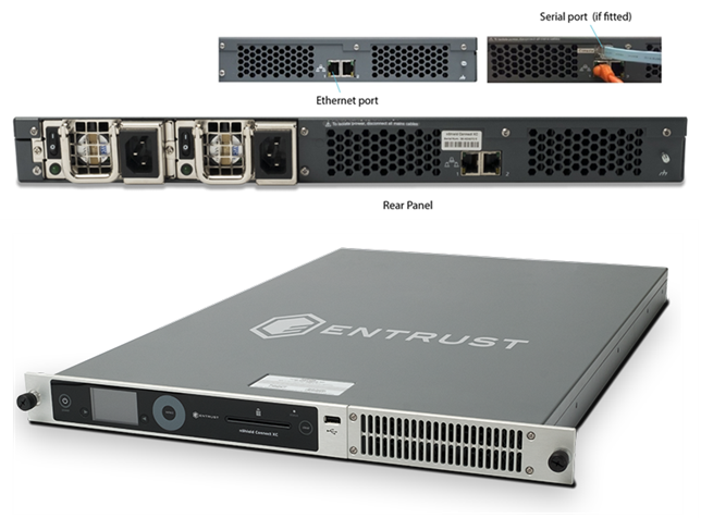
Configuring an Connect using the Serial Console
On supported Connect hardware variants (see Model numbers in the nShield Connect v12.80 User Guide (Linux)) there is an RJ45 serial port connector at the rear of the Connect marked Console. The serial port provides access to a serial console command line interface that enables remote configuration of the unit whilst also facilitating status monitoring. Tasks which would typically require a physical presence in front of the HSM, including setting IP addresses, can be done remotely using the serial console.
This functionality can help provide separation of duty between the data center technician installing the Connect and the administrator configuring and using the HSM.
The only required local activity is to connect the Connect to power and to serial and Ethernet ports.
Everything that can be configured using the front panel can then be configured remotely either over the serial interface, by using the nethsmadmin utility (see nethsmadmin) or by pushing an updated configuration file to the nShield Connect (see Configuring the Connect with configuration files).
The Serial Console supports IPv4 and IPv6 addresses.
Serial port configuration
The RJ45 connector can be directly connected to your client machine or connected to a serial port aggregator for remote access.
To access the serial console command line interface, first determine the device name of the serial connection once it is connected to your client machine. Then configure the serial port connection in your serial port communication software with the following parameters:
-
Line Speed (baud): 9600
-
Data bits: 8
-
Parity: None
-
Stop bits: 1.
Once the connection is established, press Return until a login prompt is displayed. The login prompt should look like:
nethsm login:Troubleshooting
| Error | Action |
|---|---|
Nothing on the screen |
Press Enter a few times. Make sure that the RJ45 connector is properly connected and that remote configuration is enabled on the Connect, see Enabling and disabling the serial console. |
Miscellaneous characters displayed on the screen |
Make sure the serial port connection is configured correctly, see Serial port configuration. |
Creating a serial console session
The username for accessing the serial console is cli and the default password is admin.
On first login you will be prompted to change the password for the cli user. The minimum length of the new password is 5 characters. For guidance on selecting a password, see the Connect Security Manual.
Once you are successfully logged in to a serial console session you will see the welcome message:
Welcome to the Connect Serial Console. Type help or ? to list commands.

(cli)
The serial console session will automatically logout after 180 seconds of inactivity. To manually end a session, use the logout command.
Enabling and disabling the serial console
The serial console interface can be enabled and disabled using the Connect front panel.
-
To enable the serial console interface, navigate to System > System configuration > Remote config options > Serial Console and set to On.
-
To disable the serial console interface, set Serial Console to Off.
The serial interface is enabled by default and will turn back on with the default password if the unit is reset to its factory state. This means if you do not want the serial console enabled you will need to disable it after each factory state.
If you do not see the menu option System > System configuration > Remote config options > Serial Console on the front panel then this means that your Connect does not support the serial console feature (the hardware does not support serial access).
The availability of the serial console feature can also be checked remotely from an enrolled client by running the enquiry utility.
| Feature availability | Enquiry output |
|---|---|
Serial console available |
… level six flags SerialConsoleAvailable … |
Serial console not available |
… level six flags none … |
Serial console commands
The serial console command line interface provides the following commands:
| Command | Description | ||
|---|---|---|---|
|
Get/set the HSM system time |
||
|
Prints enquiry data from the HSM |
||
|
Show the Electronic Serial Number (ESN) of the HSM |
||
|
Reset unit to its original (factory) state
|
||
|
Get/set the default IPv4 gateway address |
||
|
Get/set the default IPv6 gateway address |
||
|
List available commands with |
||
|
Show the (hash of) Kneti (used for enrolling the HSM with clients) |
||
|
Log out of the Connect Serial Console |
||
|
Get/set the IPv4 network interface configuration |
||
|
Get/set the IPv6 network interface configuration |
||
|
Get/set network interface link, Get network interface MAC address |
||
|
Get/set HSM bond interface configuration |
||
|
Get/set bond interface link |
||
|
Set the serial console password |
||
|
Ping a remote host |
||
|
Get/set the config push setting |
||
|
Reboots the HSM |
||
|
Get/set the RFS IP address and port |
||
|
Get/set IPv4 network routes |
||
|
Get/set IPv6 network routes |
||
|
Show IPv4 routing table |
||
|
Show IPv6 routing table |
||
|
Run the |
||
|
Check for any Security World data on the HSM |
||
|
Show the Connect tamper log |
||
|
Show how long the Connect has been running (since last boot) |
||
|
Show Connect Serial Console version information |
For additional help on a command, run help command to see additional guidance on command usage, syntax and parameter documentation.
Enabling optional features
nShield Connect supports a range of optional features. Optional features must be enabled with a certificate that you order from Entrust. You can order the features when you purchase a unit, or you can obtain the certificate at a later date and use the front panel of the unit to enable the features.
For more information about:
-
Ordering optional features, see Ordering additional features
-
Feature-enabling procedures, see Enabling features.
The unit firmware checks to confirm whether any features that it attempts to use are enabled. It normally does this when it authorizes the commands or command options that relate to a specific feature.
Most features are static; that is, they are enabled by means of a switch in the EEPROM of the
unit.
A dynamic feature must be enabled again if the
unit
is reinitialized.
Some optional features are static; that is, they are enabled by means of a switch in the EEPROM of the unit. A dynamic feature must be enabled again if the unit is reinitialized.
| If you are enabling the Remote Operator feature, you must enable it on the unit that is to be used as the unattended unit. For information about Remote Operator, see Remote Operator. |
Available optional features
This section lists the features that can be added to the unit. For details of all available features, contact Sales.
Elliptic Curve
Cryptography based on elliptic curves relies on the mathematics of random elliptic curve elements. It offers better performance for an equivalent key length than either RSA or Diffie-Hellman public key systems. Using RSA or Diffie-Hellman to protect 128-bit AES keys requires a key of at least 3072 bits. The equivalent key size for elliptic curves is only 256 bits. Using a smaller key reduces storage and transmission requirements.
Elliptic curve cryptography is endorsed by the US National Security Agency and NIST (the National Institute of Standards and Technology), and by standardization bodies including ANSI, IEEE and ISO.
nShield modules incorporate hardware that supports elliptic curve operations for ECDH (Elliptic curve Diffie‑Hellman) and ECDSA (Elliptic Curve Digital Signature Algorithm) keys.
Elliptic Curve activation
All nShield HSMs require specific activation to utilize the elliptic curve features. HSMs use an activator smart card to enable this feature. Refer to Enabling features with a smart card for instructions on how to enable the EC feature. Additionally it is possible to activate the elliptic curve feature without a physical smart card. In this case the certificate details can be provided by email and entered locally. Refer to Enabling features without a smart card Contact Sales if you require an EC activation.
nShield modules with elliptic curve activation support MQV (Menezes-Qu-Vanstone) modes.
Elliptic Curve support on the nShield product line
The following table details the range of nShield HSMs and the level of elliptic curve support that they offer.
| HSM module type | Elliptic Curve support | Elliptic Curve offload acceleration3 | ||
|---|---|---|---|---|
Named curves2 |
Custom curves1, 5 |
Named curves2 |
Custom curves1, 5 |
|
nShield Edge (Windows only) |
Yes |
Yes |
No |
No |
nShield Solo 500 and 6000 nShield 500, 1500 and 6000 |
Yes |
Yes |
No |
No |
nShield Solo 500+, 6000+ nShield 6000+ |
Yes |
Yes |
Yes, Prime curves and twisted Brainpool curves are accelerated4. |
Yes |
nShield Solo XC nShield Solo XC |
Yes |
Yes |
Yes, Prime curves and both twisted and non-twisted Brainpool curves are accelerated4. |
Yes |
1Accessed via nCore, PKCS#11 and JCE APIs.
2Both Prime and Binary named curves are supported. Refer to Named Curves, below, which lists the most commonly supported elliptic curves.
3Offload acceleration refers to offloading the elliptic curve operation from the main CPU for dedicated EC hardware acceleration.
4Binary curves are supported, but are not hardware offload accelerated.
5Brainpool curves are supported as named curves via nCore, PKCS#11 and JCE only.
nShield software / API support required to use elliptic curve functions
| Security World Software for nShield | CodeSafe | |
|---|---|---|
Elliptic curve supported / API |
Microsoft CNG, PKCS#11, Java Cryptographic Engine (JCE)1. |
Microsoft CNG, PKCS#11, Java Cryptographic Engine (JCE)1. |
1Java elliptic curve functionality is fully supported by the nShield security provider, nCipherKM. There is also the option to use the Sun/IBM PKCS #11 Provider with nCipherKM configured to use the nShield PKCS#11 library.
Named Curves
This table lists the supported named curves that are pre-coded in nShield module firmware.
| Supported named curves | |||
|---|---|---|---|
ANSIB163v1 |
BrainpoolP160r1 |
NISTP192 |
SECP160r1 |
ANSIB191v1 |
BrainpoolP160t1 |
NISTP224 |
SECP256k1 |
BrainpoolP192r1 |
NISTP256 |
||
BrainpoolP192t1 |
NISTP384 |
||
BrainpoolP224r1 |
NISTP521 |
||
BrainpoolP224t1 |
NISTB163 |
||
BrainpoolP256r1 |
NISTB233 |
||
BrainpoolP256t1 |
NISTB283 |
||
BrainpoolP320r1 |
NISTB409 |
||
BrainpoolP320t1 |
NISTB571 |
||
BrainpoolP384r1 |
NISTK163 |
||
BrainpoolP384t1 |
NISTK233 |
||
BrainpoolP512r1 |
NISTK283 |
||
BrainpoolP512t1 |
NISTK409 |
||
NISTK571 |
|||
Custom curves
nShield modules also allow the entry of custom elliptic curves which are not pre-coded in firmware. If the curve is Prime, it may benefit from hardware acceleration if supported by the nShield HSM (see nShield software / API support required to use elliptic curve functions, above).
Custom curves are supported by nCore and PKCS #11 APIs.
Further information on using elliptic curves
For more information on how to use elliptic curves, see the following sections:
-
PKCS #11:
-
Mechanisms supported by PKCS #11: Mechanisms
-
-
Symmetric and asymmetric algorithms: Cryptographic algorithms
-
Using
generatekeyoptions and parameters to generate ECDH and ECDSA keys: Key generation options and parameters
| Java elliptic curve functionality is fully supported by the nShield security provider, nCipherKM. There is also the option to use the Sun/IBM PKCS #11 Provider with nCipherKM configured to use the PKCS #11 library. |
Secure Execution Engine (SEE)
The SEE is a unique secure execution environment. The SEE features available to you are:
SEE Activation (EU+10) |
This SEE feature is provided with the CodeSafe developer product to enable you to develop and run SEE applications. The CodeSafe developer product is only available to customers in the Community General Export Area (CGEA, also known as EU+10). Contact Entrust to find out whether your country is currently within the CGEA. |
SEE Activation (Restricted) |
This SEE feature is provided with specific products that include an SEE application. This feature enables you to run your specific SEE application and is available to customers in any part of the world. |
For more information about the SEE, see the CodeSafe Developer Guide.
Remote Operator support
Many Entrust customers keep critical servers in a physically secure and remote location. The Security World infrastructure, however, often requires the physical presence of an operator to perform tasks such as inserting cards. Remote Operator enables these customers to remotely manage servers running Security World Software using a secure nShield communications protocol over IP networks.
The Remote Operator feature must be enabled on the module installed in the remote server. Remote Operator cannot be enabled remotely on an unattended module.
For more information about using Remote Operator, see Remote Operator.
For v12 and later, Entrust recommends that you use Remote Administration, which is more flexible than the Remote Operator functionality.
ISO smart card Support (ISS)
ISS, also called Foreign Token Open (FTO) allows data to be read to and written from ISO 7816 compliant smart cards in a manner prescribed by ISO7816-4. ISS allows you to develop and deploy a security system that can make full use of ISO 7816 compliant smart cards from any manufacturer.
Korean algorithms
This feature enables the following mechanisms:
-
Korean Certificate-based Digital Signature Algorithm (KCDSA), which is a signature mechanism.
KCDSA is used extensively in Korea as part of compliance with local regulations specified by the Korean government. For more information about the KCDSA, see the nCore API Documentation.
-
SEED, which is a block cipher.
-
ARIA, which is a block cipher.
-
HAS160, which is a hash function.
Fast RNG for ECDSA
Utilise a faster alternative for Random Number Generation (RNG) for Elliptic Curve Digital Signature Algorithm (ECDSA). This feature is applicable for Solo XC / Connect XC modules only.
The faster performance, comparable with V12.40 performance, is achieved by the RNG part of ECDSA being done on the NXP C291 Crypto Coprocessor.
This implementation of ECDSA uses an RNG that is not within scope for the Connect certifications and for this reason it will not be used when the HSM is in a fips-140-2-level-3 or common-criteria-cmts Security World (regardless of the feature bit setting).
Ordering additional features
When you have decided that you require a new feature, you can order it for your unit from Sales. Before you call Sales, you collect information about your unit as follows:
-
If possible, make a note of the unit serial number. This can be found on the base of the unit.
-
Make a note of the Electronic Serial Number of the unit. You can find this from the front panel menu, by going to HSM > HSM information > Display details.
You must provide the ESN number to order a new feature.
If you prefer, you can include this information in an e-mail to Sales.
When your order has been processed, you receive a Feature Enabling Certificate in one of the following ways:
-
Entrust e-mails you the Feature Enabling Certificate.
-
Entrust sends you a smart card that contains the Feature Enabling Certificate.
The Feature Enabling Certificate contains the information that you need to enable the features you have ordered.
For more information, including pricing of features, telephone or email your nearest Sales representative using the contact details from this guide, or contact Entrust nShield Support, https://nshieldsupport.entrust.com.
Enabling features
You must enable features from the front panel of the unit. You cannot enable them directly from the client.
| When enabling static feature(s) from the front panel, either using a card or a file, the module is cleared without warning. This will cause the HSM to drop or restart any SEE machine, and lose all the application keys that were loaded. In some cases, applications may need to be restarted. |
Viewing enabled features
To see which (if any) features have already been enabled on the Connect, from the main menu select HSM > HSM feature enable > View current state.
To print this list to a file on the unit, select HSM > HSM feature enable > Write state to file. The resulting file is transferred when the unit configuration is pushed to the remote file system.
You can find it in
/opt/nfast/kmdata/hsm-ESN/features/fet.txt
.
Enabling features with a smart card
To enable a new feature with a Feature Enabling smart card from Entrust:
-
Insert the Feature Enabling smart card into the unit’s slot.
-
From the front panel, select HSM > HSM feature enable > Read FEM from card.
A message is displayed if the features are enabled successfully. If you do not see this message confirming a successful upgrade, see Enabling features without a smart card.
Enabling features without a smart card
You can also provide the Feature Enabling Certificate information supplied by Entrust from a file.
To enable a feature without a smart card:
-
Put the file that contains the feature enabling certificate in
/opt/nfast/kmdata/hsm-ESN/featureson the remote file system. In this path,ESNis the ESN of the module.You can give the file any name that you wish. You must enter the file name on the unit’s front panel, so you may prefer to use a short name.
-
From the front panel, select HSM > HSM feature enable > Read from a file.
-
Specify the name of the file that contains the certificate.
If the feature is enabled successfully, a message confirms this.
Using multiple modules
The hardserver can communicate with multiple modules connected to the host. By default, the server accepts requests from applications and submits each request to the first available module. The server can share load across buses, which includes the ability to share load across more than one module.
If your application is multi-threaded, you can add additional modules and expect performance to increase proportionally until you reach the point where cryptography no longer forms a bottleneck in the system.
Identifying modules
Modules are identified in two ways:
-
By serial number
-
By
ModuleID.
You can obtain the ModuleID 's and serial numbers of all your modules by running the enquiry command-line utility.
Electronic Serial Number (ESN)
The serial number is a unique 12-digit number that is permanently encoded into each module. Quote this number in any correspondence with Support.
ModuleID
The ModuleID is an integer assigned to the module by the server when it starts.
The first module it finds is given a ModuleID of 1, the next is given a ModuleID of 2, and this pattern of assigning ModuleID numbers continues for additional modules.
The order in which buses are searched and the order of modules on a bus depends on the exact configuration of the host. If you add or remove a module, this can change the allocation of ModuleIDs to all the modules on your system.
You can use the enquiry command-line utility to identify the PCI bus and slot number associated with a module.
All commands sent to nShield modules require a ModuleID. Many Security World Software commands, including all acceleration-only commands, can be called with a ModuleID of 0. Such a call causes the hardserver to send the command to the first available module.
If you purchased a developer kit, you can refer to the developer documentation for information about the commands that are available on nShield modules.
In general, the hardserver determines which modules can perform a given command. If no module contains all the objects that are referred to in a given command, the server returns an error status.
However, some key-management operations must be performed together on the same module.
In such cases, your application must specify the ModuleID.
To be able to share OCSs and keys between modules, the modules must be in the same Security World.
Adding a module
If you have a module installed, you can add further modules without reinstalling the server software.
However, we recommend that you always upgrade to the latest server software and upgrade the firmware in existing modules to the latest firmware.
| Before you install new hardware, check the release notes on the installation media supplied with your new module for information about specific compatibility issues, new features, and bug fixes. |
-
Install the module hardware. Refer to the Installation Guide for information on installing nShield hardware.
-
Run the script
/opt/nfast/sbin/install. -
Add the module to the Security World. Refer to Adding or restoring an HSM to the Security World.
Module fail-over
The Security World Software supports fail-over: if a module fails, its processing can be transferred automatically to another module provided the necessary keys have been loaded. Depending on the mode of failure, however, the underlying bus and operating system may not be able to recover and continue operating with the remaining devices.
To maximize uptime, we recommend that you fit any additional nShield modules for failover on a bus that is physically separate from that of the primary modules.
Stopping and restarting the hardserver
If necessary, you can stop the hardserver on the client, and where applicable the Remote Administration Service, by running the following command:
/opt/nfast/sbin/init.d-ncipher stopSimilarly, you can restart the hardserver on the client, and where applicable the Remote Administration Service, by running the following command
/opt/nfast/sbin/init.d-ncipher startResetting and testing the Connect
Default configuration
To reset the unit to its default configuration, select System > System configuration > Default config and confirm that you want to set the default configuration.
This removes the configuration of the module but does not change its KNETI.
Factory state
To reset the unit to its original (factory) state, select Factory state from the main menu and confirm that you want to return the unit to its factory state.
This gives a new KNETI to the unit, which means that you must update the keyhash field of the unit’s entry in the nethsm_imports section of the configuration file of all the clients that use it.
For more information about:
-
The contents of the configuration files, see Module and client configuration files
-
Configuring a new remote file system for the unit, see Configuring the Remote File System (RFS).
Testing the installation
To test the installation and configuration, follow these steps:
-
Log in on the client computer as a regular user, and open a command window.
-
Run the command:
opt/nfast/bin/enquiryA successful
enquirycommand returns an output of the following form:Server: enquiry reply flags none enquiry reply level Six serial number ####-####-#### mode operational version #-#-# speed index ###### rec. queue ####..#### --- version serial # remote port (PV4) #### Module ##: enquiry reply flags none enquiry reply level Six serial number ####-####-#### mode operational version #-#-# speed index ##### rec. queue ##..### --- rec. LongJobs queue ## SEE machine type PowerPCELF supported KML types DSAp1024s160 DSAp3072s256 hardware status OKIf the mode is
operational, the unit is installed correctly.If the
enquirycommand says that the unit is not found:-
Restart the client computer.
-
Re-run the
enquirycommand.
-