Before installing the module
Back panel and jumper switches
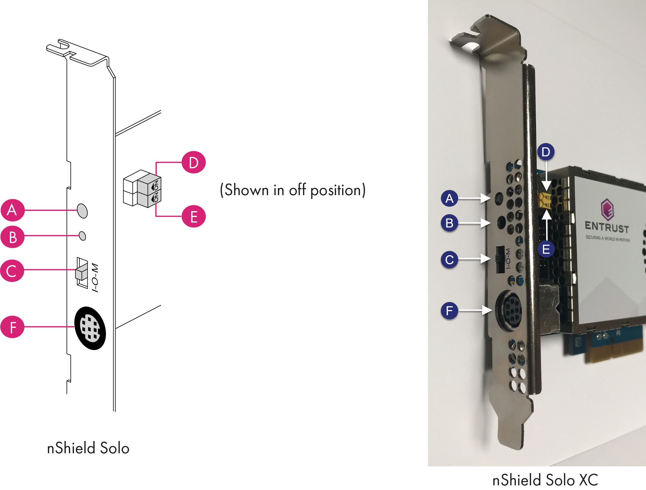
| Label | Description |
|---|---|
A |
Status LED |
B |
Solo, Solo XC: Recessed clear button nShield 5s: Recovery mode button |
C |
Physical mode switch |
D |
Physical mode override jumper switch, in the Off position. When set to On, the mode switch (C) is deactivated. See the User Guide for more information. |
E |
Remote mode override jumper switch, in the Off position. When set to On, remote mode switching is disabled. See the User Guide for more information. |
F |
A mini-DIN connector for connecting a smart card reader. |
| The configuration of connectors varies between modules and might not be as in the image. |
Module pre-installation steps
Check the module to ensure that there is no sign of damage or tampering:
-
Check the epoxy resin security coating, or the metal lid for the Solo XC, for obvious signs of damage.
-
If you intend to install the module with an external smart card reader, check the cable for signs of tampering. If evidence of tampering is present, do not use and request a new cable.
-
Solo and Solo XC only
Check that the two jumper switches are in the required positions.
-
The physical mode switch must be set to Operational (O) to be able to use the remote mode switch override to change the mode. To use the Remote Administration feature to be able to change the mode of the module remotely, ensure that the jumper switch (E) is in the off position and the physical mode switch (C) is set to Operational (O).
The default factory setting of the jumper DIP switch E is Off. This enables remote MOI switching. Factory shipping nShield Solo HSMs loaded with firmware 2.61.2 or greater will support remote MOI switching by default. Customers who expressly do not want to enable the remote MOI switching capability must switch jump switch E to the On position.
Fitting a module bracket
Before installing a module in a PCI-Express card slot, you may have to replace the bracket if it is not the same height as the slot. Both full height and low profile brackets are supplied with the module.
Do not touch the connector pins, or the exposed area of the module without taking ESD precautions.
To fit the bracket to the module:
-
Remove the two screws from the solder side of the module.
-
Remove the incorrect bracket.
-
Fit the correct bracket to the component side of the module.
-
Insert the two screws into the solder side of the module to secure the bracket. Do not over tighten the screws.
Replace the fan - Solo XC only
Required Tools
-
Phillips screwdriver #0
-
Phillips screwdriver #2
-
Small needle nose pliers
Required Part
-
Orderable part number SOLOXC-REP-FAN (Replacement fan assembly).
-
Power off the system and while taking ESD precautions, remove the Solo XC card.
-
Place the Solo XC on a flat surface.
-
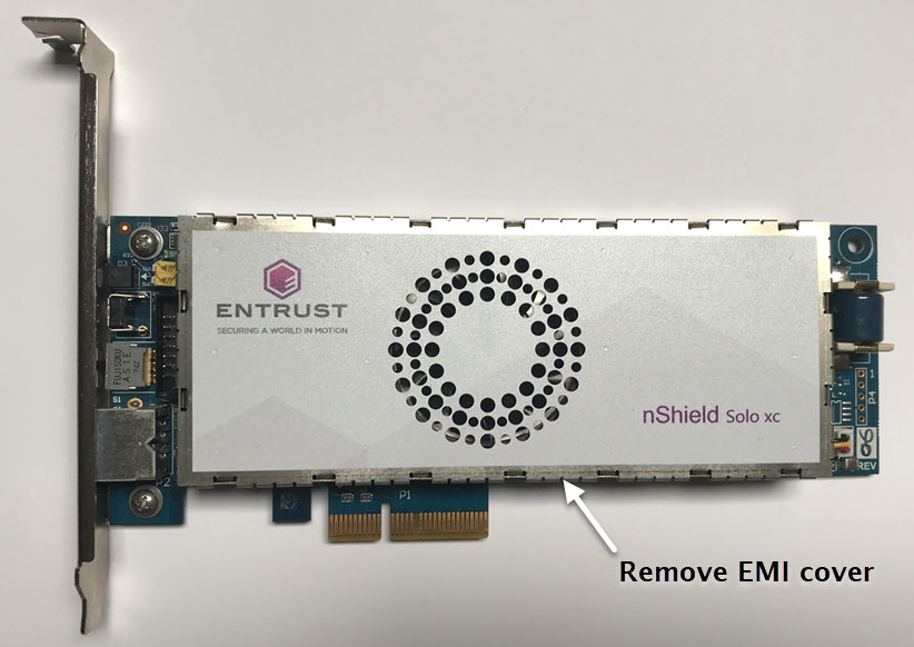
Remove the top EMI cover using a #2 screwdriver.
-
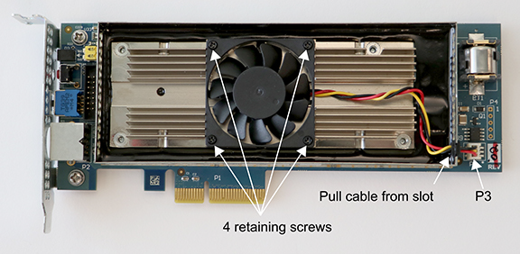
Pull the fan power cable and grommet from the slot in the EMI fence.
-
Using the needle nose pliers, gently remove the fan power cable from the P3 connector.
-
Using the #0 Phillips screwdriver, remove the four fan retaining screws.
-
Remove the defective fan from the Solo XC and install the replacement fan with the power cable positioned towards the P3 power connector. Ensure that the fan lays flat against the heatsink.
-
Replace the four fan retaining screws.
-
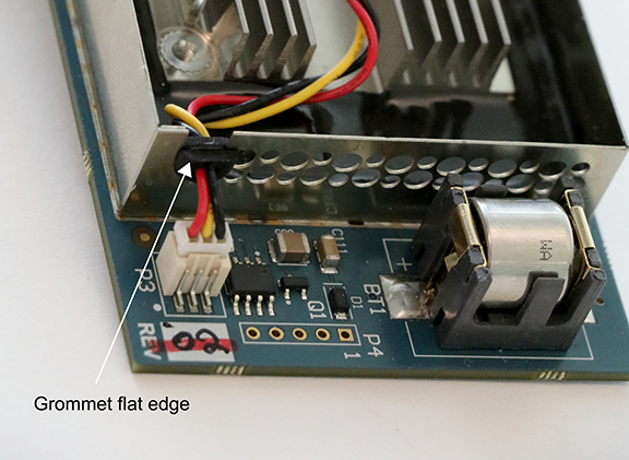
Install the power cable connector into the Solo XC P3 power connector.
-
Install the power cable grommet into the slot in the EMI fence, with the flat side towards the top of the fence.
-
Replace the top EMI cover.
-
Re-install the Solo XC into the PCIe slot.
-
Replace the battery - Solo XC and nShield 5s
| Please follow battery disposal guidelines in the installation manual. |
Required tools
-
Small non-conductive tweezers
Required part for both Solo XC and nShield 5s
-
Orderable part number: SOLOXC-REP-BATT (Replacement battery)
To remove and replace the battery:
-
Power off the system and while taking ESD precautions, remove the module.
-
Place the module on a flat surface.
-
Using the tweezers, gently remove the battery from the BT1 connector.
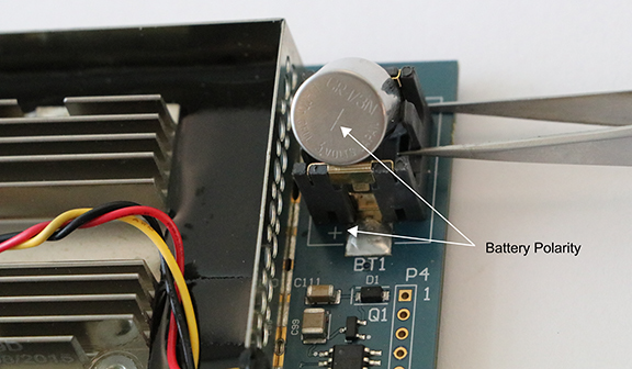
-
Observing the polarity, install the replacement battery in the BT1 connector.
-
Re-install the module into the PCIe slot.