Install a network-attached HSM into a rack
This guide covers the following HSMs:
-
nShield Connect
-
nShield 5c
-
nShield 5c 10G
| Always handle modules correctly. Take due account of the weight and dimensions of the HSM when selecting a location for storage or installation. For more information, see Handling an HSM. |
| You cannot install or configure the HSM remotely. |
To install the HSM in a 19” rack, follow the instructions supplied with your rack mounting kit.
To install the HSM in a cabinet or a shelf, fit self-adhesive rubber feet to the bottom of the HSM, one in each corner.
| If you encounter any problems during the install process, refer to Troubleshooting. This page includes explanations for the status LED, log messages, and audible warnings as well as other information. |
Connecting Ethernet, console and power cables
The connectors for Ethernet cables and mains power cables are at the rear of the HSM.
Ensure that:
-
All power cables are routed to avoid sharp bends, hot surfaces, pinches, and abrasion.
-
You connect mains power cables to both the PSUs.
-
The rocker switch for each PSU is in the on position.
nShield Connect and nShield 5c
The HSM is an Ethernet network device capable of supporting up to 100m of Ethernet cable. You must use a CAT5e UTP cable or better when connecting the HSM to a 100Mbit or 1Gbit Ethernet device. You must use a CAT3 cable or better for 10Mbit connections.
The following image shows the Ethernet, console and mains power connections:

| Key | Description |
|---|---|
A |
Green LED if on, confirms power is on and unit is not in Standby mode |
B |
Mains power connection |
C |
Rocker switch to turn PSU on and off |
D |
Ethernet port. Two Ethernet ports are available. Port 1 is the left-hand connector when the HSM is viewed from the back |
E |
RJ45 port for a serial console cable |
If you connect only one network cable to the HSM, connect it to network port 1. This is the left-hand Ethernet connector on the rear of the HSM (shaded in the image).
If the green LED is on, the PSU is operational and receiving power, and is not in Standby mode. If a power cable is not fitted correctly, or a rocker switch is not turned on, an audible warning is given and the orange warning LED on the front panel is turned on.
For more information:
-
Audible warnings, see Audible warning.
-
The orange warning LED, see Orange warning LED.
-
Identifying and replacing a faulty PSU, see the HSM Power Supply Unit Installation Sheet.
nShield 5c 10G
The HSM is an Ethernet network device. The cable lengths and speeds it will support depend on the SFP+ transceivers used. Entrust recommends you use the SFP+ modules detailed in SFP+ transceivers and refer to the manufacturer documentation for the interconnection and physical layer specifications. These modules have been qualified for use with the nShield 5c 10G.
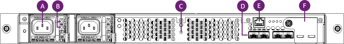
| Key | Description |
|---|---|
A |
Mains power connection |
B |
Two dual-colour status LEDs for the mains power connection. They are steady green in normal operation and amber or blinking green for various fault conditions.
|
C |
Diagnostic LED |
D |
4 SFP+ 10G ports Plug the SFP+ transceiver into the port before you connect the ethernet cable. If you connect only one Ethernet cable to the HSM, Entrust recommends that you connect it to an SFP transceiver in port 1. For more information on SFP transceivers, see SFP+ transceivers. |
E |
RJ45 port for a serial console cable |
F |
Battery module Do not remove the battery module for longer than 15 minutes at a time. See nShield 5c 10G maintenance. |
nShield 5c 10G network profiles
The nShield 5c 10G has four ports that accept pluggable transceivers and offer copper or fiber connectivity.
This enables port-based separation of different types of network traffic:
Ports 1 and 2 (eno1 and eno2) are management interfaces, ports 3 and 4 (eno3 and eno4) are the data interfaces.
It isolates management services (traffic to and from the platform) from the cryptography services (traffic to and from a tenant).
Previous HSM models, such as Connect XC and 5c support separate IP configurations but do not offer traffic separation.
You can set the network profile of the 5c 10G to one of the following configurations:
| Profile | eno1 |
eno2 |
eno3 |
eno4 |
|---|---|---|---|---|
Single port (default) |
Mgmt + Data |
- |
- |
- |
Bonded ports |
Mgmt + Data, bonded |
- |
- |
|
Separated ports |
Mgmt |
- |
Data |
- |
Separated and bonded ports |
Mgmt, bonded |
Data, bonded |
||
You can manage the profile types using KeySafe 5 or through the serial CLI.
-
On the serial CLI, you can give the single profile a static IPv4 or IPv6 configuration. Other profiles or pairs of ports can then be configured using KeySafe 5.
-
In all profiles the default configuration enables DHCPv4 and SLAAC.
-
In the bonded and separated and bonded profiles, pairs of interfaces can be bonded together using either active backup or 802.3ad bonding modes. The configuration of each bonding is independent.
To see what settings are user-configurable, see nShield HSM configuration files.
Example: Non-separated profile
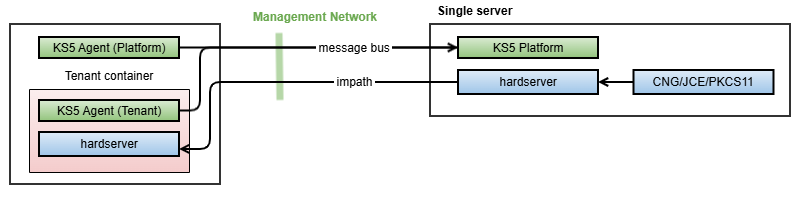
This is a simple deployment with non-separated network traffic, using either the single port or bonded ports profiles. All device management operations and security world operations are performed within the single KeySafe 5 server. The single server is also running the hardserver and the existing CSPs (PKCS11/JCE/CNG) but either component can be deployed on separate systems that are routable from the 5c 10G’s management interfaces.
Example: Separated profile
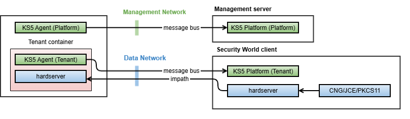
This is network port-level service separation, using either the separated ports or separated and bonded ports profiles.
-
Device management is performed through the management network, using one instance of the KeySafe 5 server. This is where all network configuration, system logging, and configuration of tenants is performed.
-
Security world management and crypto operations are performed on the data network, directly on the security world client and in the tenant KeySafe 5 instance.
Connecting the Serial Console
On supported HSM hardware variants (see Model numbers) there is a serial console port that provides access to a serial console command line interface that enables remote configuration of the HSM.
The Serial console port is always available on the nShield 5c 10G.
The RJ45 connector for the serial cable is at the rear of the HSM and is labelled Console, see Connecting Ethernet, console and power cables. The connector can be directly connected to your client machine or connected to a serial port aggregator for remote access. For a specification of the serial cable required, see Serial Console cable pinout information. The serial port will operate at 115200 baud, 8 data bits, no parity, and 1 stop bit (115200/8-N-1).
Serial Console cable pinout information
The pinout information for the RJ-45 to DB-9 cable to be used to access the HSM Serial Console is provided in the table below:
| Signal | Console Port (DTE) RJ-45 Pin | Adapter DB-9 Pin | Signal |
|---|---|---|---|
CTS |
1 |
7 |
RTS |
DTR |
2 |
4 |
DSR |
TxD |
3 |
3 |
RxD |
GND |
4 |
5 |
GND |
GND |
5 |
5 |
GND |
RxD |
6 |
2 |
TxD |
DSR |
7 |
6 |
DTR |
RTS |
8 |
8 |
CTS |
Connecting the optional USB keyboard (nShield Connect and nShield 5c)

Instead of using the controls on the front panel to configure the HSM, you can use a US or UK keyboard. You might find a keyboard easier for entering dates and IP addresses. You connect the keyboard to the USB connector on the front of the HSM.
Configuring an HSM for your keyboard type
To configure an HSM for your keyboard type, select System > System configuration > Keyboard layout and then choose the keyboard type you require.
When you have connected a keyboard and configured the HSM for its use, you can enter numbers and characters directly into the display. See Using a keyboard to control the unit for more about using a keyboard and keystroke shortcuts.